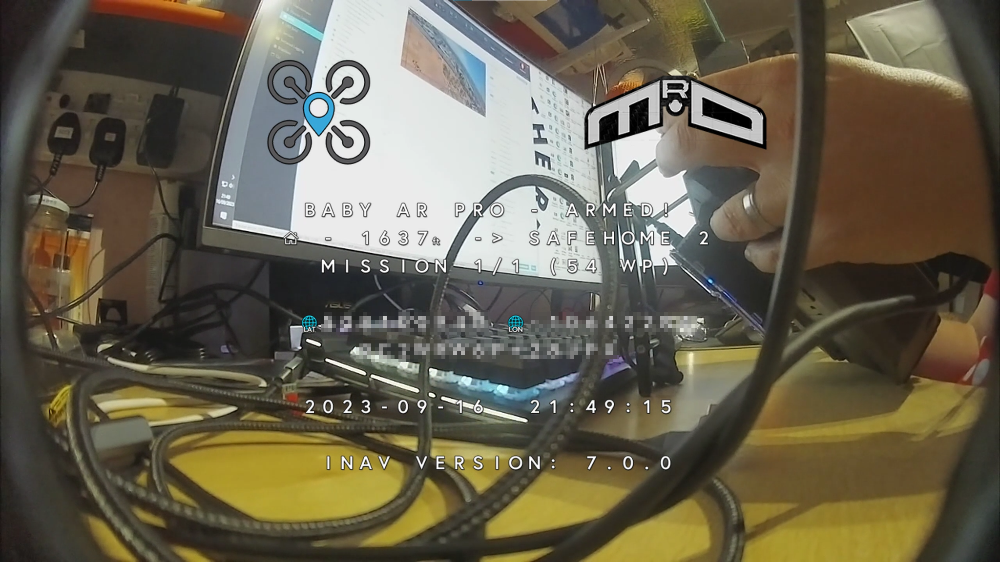
On Screen Display (OSD)
The On Screen Display, or OSD, is a feature that overlays flight data over the video image. This can be done on the flight controller using the analogue MAX7456 chip. Digital systems take the OSD data via MSP DisplayPort, send it to the video receiver, which then combines the data with the image. You can specify what elements are displayed and their locations on the image. Most analog systems are character based and use the MAX7456, or use MSP DisplayPort if digital. However, there additional systems which are also supported such as the canvas based FrSKY PixelOSD for an analogue OSD. Canvas OSDs draw shapes on the image whereas character based OSDs use font characters to display the data.
General OSD information is in this document. Other documents cover specific OSD-related topics:
OSD Types and Features
Not all OSDs are created equally. This table shows the differences between the different systems available.
| OSD System | Character grid | Character | Canvas | MSP DisplayPort | All elements supported |
|---|---|---|---|---|---|
| Analogue PAL | 30 x 16 | X | YES | ||
| Analogue NTSC | 30 x 13 | X | YES | ||
| PixelOSD | As PAL or NTSC | X | YES | ||
| DJI OSD | 30 x 16 | X | NO - BF Characters only | ||
| DJI WTFOS | 60 x 22 | X | X | YES | |
| HDZero | 50 x 18 | X | X | YES | |
| Avatar | 53 x 20 | X | X | YES | |
| DJI O3 Goggles V2 + WTFOS | 53 x 20 | X | X | YES | |
| DJI Goggles 2 and newer | 53 x 20 (HD) | X | X | YES (no custom fonts) |
OSD Elements
INAV supports a number of different parameters that can be displayed on the OSD as elements. The list of elements can be viewed in the appendix
Pilot Logos
From INAV 7.0.0, pilots can add their own logos to the OSD. These can appear in 2 places: the power on/arming screens or as an element on the standard OSD. Please note that the power on/arming screen large pilot logos are only available on HD systems.
To use the pilot logos, you will need to make a custom font for your OSD system. Base fonts and information can be found in the OSD folder in the Configurator resources. Each system will need a specific method to create the font image files. So they will not be covered here. There are two pilot logos.
 The small pilot logo appears on standard OSD layouts, when you add the elemement to the OSD screen. This is a 3 character wide symbol (characters 469-471).
 The large pilot logo appears on the power on and arming screens, when you enable the feature in the CLI. To do this, set the
 osd_use_pilot_logo parameter to on. This is a 10 character wide, 4 character high symbol (characters 472-511).
General Settings
osd_arm_screen_display_timeThe amount of time the arming screen is displayed.osd_inav_to_pilot_logo_spacingThe spacing between two logos. This can be set to0, so the original INAV logo and Pilot Logo can be combined in to a larger logo. Any non-0 value will be adjusted to best align the logos. For example, the Avatar system has an odd number of columns. If you set the spacing to 8, the logos would look misaligned. So the even number will be changed to an odd number for better alignment.osd_use_pilot_logoEnable to use the large pilot logo.
Examples
This is an example of the arming screen with the pilot logo enabled. This is using the default settings.
This is an example of setting the osd_inav_to_pilot_logo_spacing to 0. This will allow a larger, single logo.
Post Flight Statistics
The post flight statistcs are set in the firmware. Statistics are only hidden if the supporting hardware is not present. Due to size contraints. The post flight statistics are spread over 2 pages on analogue systems.
Statistics Shown
| Statistic | Requirement | Page | |
|---|---|---|---|
| Flight Time | 1 | The total time from arm to disarm. | |
| Flight Distance | 1 | ||
| Maximum Distance From Home | GPS | 1 | |
| Maximum Speed | GPS | 1 | |
| Average Speed | GPS | 1 | |
| Maximum Altitude | Baro/GPS | 1 | |
| Minimum Average Cell Voltage | 1 | ||
| Minimum Pack Voltage | 1 | ||
| Maximum Current | Current Sensor | 1 | |
| Maximum Power | Current Sensor | 1 | |
| Energy Used (Flight) | Current Sensor | 1 | |
| Energy Used (Battery Total) | Current Sensor | 1 | This data is not reset on arming. |
| Average Efficiency | Current Sensor & GPS | 1 | |
| Minimum RSSI | 2 | ||
| Minimum LQ | CRSF | 2 | |
| Minmum dBm | CRSF | 2 | |
| Minimum Satellites | GPS | 2 | |
| Maximum Satellites | GPS | 2 | |
| Minimum ESC Temperature | ESC Telemetry | 2 | |
| Maximum ESC Temperature | ESC Telemetry | 2 | |
| Maximum G-Force | 2 | ||
| Minimum Z axis G-Force | 2 | ||
| Maximum Z axis G-Force | 2 | ||
| Blackbox file number | Blackbox recording | 2 | |
| Disarm method | 1 & 2 | ||
| Settings save status | 1 & 2 | Shows a message if the settings are being saved or have been saved on disarm. |
Configuration
There are a couple of settings that allow you to adjust parts of the post flights statistics.
osd_stats_page_auto_swap_timeallows you to specify how long each stats page is displayed [seconds]. Reverts to manual control when Roll stick used to change pages. Disabled when set to 0.osd_stats_energy_unitallows you to choose the unit used for the drawn energy in the OSD stats [MAH/WH] (milliAmpere hour/ Watt hour). Default is MAH.osd_stats_show_metric_efficiencyif you use non-metric units on your OSD. Enabling this option will also show the efficiency in metric.
Custom OSD Elements
From INAV 7.0.0, support for the creation of custom OSD elements was made possible. This allows users to add their own elements and display relevant data derived from the Programming framework.
The settings are found under the Configurator OSD tab. The layout has changed slightly in INAV 8.0.0.
Each custom OSD element has three configurable spaces (eight in INAV 8.0.0), with each having an activation condition. You're not required to use all the configuration custom spaces if all elements are active. The custom configurable spaces can either be a character from the OSD font, data from the programming framework, or text. The character numbers can be found in the appendix for character map.
These are the options available in each configurable space.
| Options | Description |
|---|---|
| None | Don't use any selection in the drop-down |
| Text | Displays text. 0 - 15 characters which can include [A-Z] [0-9] [^!.\*] * Text can only be used once in a single element, due to memory limitations |
| Icon Static | User can select a character number from the INAV OSD , they want to display as a descriptive reference |
| ICON from Global Variable | Displays the icon, driven from a global variable |
| ICON from Logic Condition | Displays the icon, driven from a logic condition (Added in INAV 8.0.0) |
| Global Variable # | Data within the global variable can be displayed in these decimal format's [00000 0000 000 00 0 0000.0 000.00 000.0 00.00 00.0 0.0] (Some formats added in INAV 8.0.0) |
| Logic Condition # | Status of the logic condition can be displayed in these decimal format's [00000 0000 000 00 0 0000.0 000.00 000.0 00.00 00.0 0.0] (Added in INAV 8.0.0) |
| VISIBILITY | Choose when to display custom message - Always or as the result of a Global Variable or Logic Condition being met |
Currently, only the first 255 characters are supported by custom OSD elements.
Please refer to this video made by the features' developer. It shows an example of a custom element, which is the !GROUND! message, and a GV containing Lidar altitude above the surface with a static altitude character beside it.
Working with numbers
You may have noticed that there are plenty of different options for showing different formats of numbers. All numbers can be either positive or negative. This is why there is an empty space to the left of a positive number. Integers are self explanatory: simply choose the appropriate number of digits for the number you are displaying. For real numbers with decimal places, extra configuration is necessary. In the programming framework, there are no floating point numbers thus no decimal spaces. So how do we display a number with decimal spaces? We are simply faking it with maths and rudimentary dimensional analysis.
As an example, let's say we want to show our distance to home in kilometres. The Flight - Home distance [m] operand in the programming framework returns metres. Suppose we also want to show 2 decimal places. How do we do it? Simply, take the calculation we would normally need and shift it by the number of decimal places. For example, to convert our metres to kilometres, we need to divide the metres by 1000. Since we want two decimal places, we shift the 1000 we use for the calculation right by 2. Instead of performing metres ÷ 1000, we perform metres ÷ 10.
As a concrete example, imagine that Flight - Home distance [m] is outputting 7243m. All results are whole numbers, so 7243 ÷ 10 = 724. Our custom OSD element display then takes that number and inserts the decimal place in the correct place. This results in our OSD showing 7.24km.
Example: Simple stall warning indicator
The logic checks if the Pitch is above 20°, and the Virtual Airspeed has dropped below 35km/h, or the Throttle has been reduced below 48%. When those hard coded conditions are met, the warning of a potential stall is triggered. Since most tip stall conditions are induced unknowingly by the pilot, this can help avoid such events.
Make sure to enable the Virtual Pitot if you do not use a real Pitot. To better suit your aircraft. Pitch angle, Airspeed and Throttle/Delay values should be altered for best detection.
The message will display STALL WARNING with a warning symbol (221). The stall message will only appear when the conditions are met.
Please note that stalls are not caused directly by the speed of the aircraft. Stalls are caused by too little airflow over the wing, which is dependent on airspeed at the attitude of the aircraft. The stall warning example above may not detect all instances of a stall. Please do not be complacent. Aircraft with higher wing loading or poor stall characteristics should always be flown with caution when lowering the throttle to conserve energy.
Example: Basic Switch Indicator
While there are switch indicators for the OSD, using custom OSD elements can give much more control over this.
On the Programming Framework page. Set up the Logic Conditions for the switch.
- LC0 takes the channel that you want to display the switch for, and subtracts 1000. This gives the switch a 0-1000 range.
- LC1 maps that range to 3 values: 0, 1, and 2.
- LC2 Adds the value from LC1 to the first switch indicator icon. 208 is switch down, 209 is switch in the middle, and 210 is switch up.
- LC3 sets GVAR 0 to the value from LC2. Note In INAV 8.0.0, you do not need LC3. You can use the output from LC2 directly to select the icon.
Then on the OSD page, add the dustom OSD element to handle the programming.
- Setup the icon. For INAV 7.1.x you will need to set this to Icon Global Variable. You would set the GV to the variable you chose in the programming. In this example, GV 0. With INAV 8.0.0 onwards, we don't need to use the Global Variable. So set this to use Icon from Logic Condition. Then set the LC to the appropriate Logic Condition. LC2 in our example.
- Next, we simple add the Text for what the switch represents.
If you want to swap the icon and text sides. You simply switch the text and icon.
Please note that Custom element previews are added in INAV 8.0.0. Currently, the Custom OSD icons in the OSD preview cannot retrieve the actual value from the global variable. The actual value of Global Variable 0 in the above example is 209. Which displays the mid switch position
![]()
Example: Showing the altitude in different measurement units
In this example, we have our OSD set to metric. Since some only understand feet, we will rectify the problem by displaying both imperial and metric units. We have the standard Altitude OSD element showing us the altitude in metres. Then we are going to add a second altitude custom element in feet. First, hop to the Programming page and we will perform the calculations.
The first LC, we multiply the altitude in cm by 100. This allows us to divide with more accuracy. For the second LC, we are dividing the result of LC0 by 3048 to get the result in feet. Note that by multiplying by 100 and dividing by 3048, we are more accurate, but will max out at 7045ft. Of course, we're not flying anywhere near that altitude. This calculation is just to show the limitations.
Next, head back to the OSD page and enable Custom Element 1. We will now make this show the altitude in feet.
In the first configuration space, we choose Logic Condition 0000 from the list. We will now choose LC1, which is the logic condition performing the divide. We can use 4 digits of precision because we know the number will not go over 7045. Next, we select Static Icon for the seconds configuration space. The character number is 120, so enter that. You can see that the OSD preview has updated and is showing the a 4 digit number and the correct Alt Ft character.
What if we only wanted to this altitude when we are under 400ft for example. We can do this by adding one more line on the Programming page:
The third logic condition is only active if we are below 400 feet. So back on the OSD page. We can change the visibility configuration to Logic Condition and LC2. This will only show our custom element when the altitude is below 400 ft.
Custom OSD Elements video tutorials
How to add custom OSD elements in INAV - Mr.D RC
HUD AND ESP32 Radar
The HUD is a feature that displays various points of interest (POI) on the OSD, in "3D", by showing a marker where the location is on the screen. For now it's capable to display :
- The home point
- Nearby aircrafts as sent by an ESP32 LoRa modem
- Next waypoints during a mission.
Later updates
- INAV 6.0 - Seen an update in the way the Craft radar information is display on the OSD. Craft radar layout
- INAV 8.0 - Provides the ability to display the Craft radar in a fix location on the OSD. Without using the HUD, which is still an option.
- FormationFlight project.
Video Resources
- This is a video demonstrating the hud for both home point and ESP32 radar tracking.
- This is a video demonstrating the display of the waypoints live during an autonomous mission.
Configuration
The HUD must be set from the CMS menu of the OSD or from the CLI in the Configurator.
Important! The HUD is a sub-set of the crosshair, it's designed this way because the crosshair is the origin/reference for anything hud-related.
- So make sure you enable the Crosshair in the configurator OSD tab, if you wish to display any HUD related information, including the Craft Radar.
- You are NOT required to select the Crosshair if you use the
INAV radar fixedelement. Its selected in the OSD tab under Maps & Radar. It can be beneficial when using the Craft Radar on multicopter platforms.
It is not recommended to have any of the legacy map or 2D-view items displayed in your OSD, as this could cause overlaps on the screen. In order for the HUD to display in "3D" where the POI is, it needs to know few things about your FPV camera :
In the CMS/OSD menu, go to OSD > HUD >...
Crosshair style
To choose between 7 different types of crosshairs.
CLI :
osd_crosshairs_style = DEFAULT
Available Values: DEFAULT, AIRCRAFT, TYPE3, TYPE4, TYPE5, TYPE6, TYPE7
Camera Uptilt
Set the camera uptilt for the FPV camera. That's the angle in degres between the horizontal of the aircraft and the line of sight of the camera. For a multirotor with a camera usually pointing up it's a positive value, most often between 5 and 30°. For a plane with the camera pointing down it should be a negative value, often between -5 and -10°.
CLI :
osd_camera_uptilt = 0
Camera FOV horizontal + vertical
The FOV for the FPV camera, the default values are ok for a 2.8mm lens. If your camera is a 2.5mm or 2.1mm or lower focal, try to raise both the horizontal and vertical FOVs by 5 or 10° by steps (the smaller the focal length, the larger the field of view). If the FOV is too far off, the tracking won't work well near the borders of the screen.
CLI :
osd_camera_fov_h = 135
osd_camera_fov_v = 85
Hud Margin horizontal + vertical
How far from the border of the screen the hud ends, so it does not overwrite the rest of your OSD datas.
CLI :
osd_hud_margin_h = 3
osd_hud_margin_v = 3
Horizon offset
To vertically adjust, between -2 and +2, the whole OSD and AHI and scrolling bars, it's recommended to leave it at 0.
CLI :
osd_horizon_offset = 0
Displayed items:
This sub menu will let you select what is displayed on the Hud :
Homing arrows
To display little arrows around the crossair showing where the home point is.
CLI :
osd_hud_homing = ON
Home point
To 3D-display the home point location (H)
CLI :
osd_hud_homepoint = ON
Radar max aircraft
Maximum count of nearby aircrafts or POIs to display, as sent from an ESP32 LoRa module. Set to 0 to disable (show nothing), up to 4. The nearby aircrafts will appear as markers A, B, C, D
CLI :
osd_hud_radar_disp= 3
Radar min range
In meters, by default 10 meters, radar aircrafts closer than this will not be displayed. This setting exists mostly to unclutter the OSD view during close range pursuits.
CLI :
osd_hud_radar_range_min = 10
Radar max range
In meters, by default 4000, radar aircrafts further away than this will not be displayed.
CLI :
osd_hud_radar_range_max = 4000
Next waypoints
How many waypoint are displayed, from 0 to 3. Set to 0 (zero) to disable. As sample, if set to 2, and you just passed the 3rd waypoint of the mission, you'll see markers for the 4th and waypoints (marked "4' and '5')
This is a video demonstrating the display of the waypoints live during an autonomous mission.
CLI :
osd_hud_wp_disp= 2
CLI commands
All the settings are available in the CLI, recommended settings are :
set osd_crosshairs_style = DEFAULT
set osd_horizon_offset = 0
set osd_camera_uptilt = 0
set osd_camera_fov_h = 135
set osd_camera_fov_v = 85
set osd_hud_margin_h = 3
set osd_hud_margin_v = 3
set osd_hud_homing = OFF
set osd_hud_homepoint = OFF
set osd_hud_radar_disp = 3
set osd_hud_radar_range_min = 10
set osd_hud_radar_range_max = 4000
set osd_hud_wp_disp = 2
Craft radar layout
The radar layout is the same for both Analog and Digital. However digital can be in color and requires a video system that fully supports the INAV font set. Which DJI does not provide at the time of writing this. Meaning it will not have a full compliment of OSD elements, as in the image below.
There can be some confusion concerning the use of (1) The peer aircraft's heading arrow. You may know the direction the peer aircraft is located by (5) The Cardinal pointer e.g. 2 O'clock. But without the heading arrow, you will not know whether that aircraft is traveling towards you, away from you, or across your aircraft's line of flight. So by using both the Cardinal pointer and the Heading arrow reference of the other aircraft, you can set a heading that will help you intersect the other aircraft more quickly.
Accuracy and limitations
There's a long chain of inaccuracies conspiring to make the tracking not perfectly accurate :
-
The heading of your aircraft can be wrong by a significant margin during, or right after a hard turn. The steadier the flight, the more accurate it is.
-
Accurate positioning for the POI markers depends on the actual attitude and heading of the aircraft, any slight difference of few degrees will mess up the tracking.
-
The tracking is not taking into account the roll angle of the plane so it remains simple and fast, so it won't be accurate when the banking angle is too high.
-
The OSD is character based and not pixel based. Limited by grid size.
-
The analog crosshair is not perfectly centered in both horizontal and vertical dimensions because of an even numbers of columns and rows.
-
The position of the other aircrafts as sent by the ESP32 modules are updated at 2Hz (10Hz with FormationFlight), so at high speed there's lag involved because of relative movements.
ESP32 LoRa modem ("INAV Radar" project)
If you have such a module fitted on your aicraft, extra steps are required in order to display the remote aircrafts live on the Hud :
-
Wire the ESP32 module to a free UART on your flight controller, same as you would connect a GPS (+5V, GND, TX, RX). Using a Softserial port is not supported, it's not fast enough.
-
In the INAV Configurator, Ports tab, enable the MSP option for this UART, and set the speed to 115200. You don't have to set anything else for the port, the ESP32 will then communicate with the flight controller using standard MSP/MSP2 messages.
-
In the CMS, OSD > Hud > Displayed items, set Radar max aircraft to 4
-
If the wiring and port configuration is correct, at boot time the ESP32 module will show the INAV/host version detected.
Please see this discussion at RCGroups for mode details about the ESP32 modules and the radar project.
This is a video demonstrating the hud for both home point and ESP32 radar tracking.
Formation Flight
The FormationFlight project is separate to INAV ESP32 Radar. Both firmware's provide a means of RF communication between multiple aircraft.. But its more versatile, using the same hardware as the ELRS project. And has many advantages over the original Lora ESP32 boards. Being that the hardware is smaller, lighter and cheaper. The INAV project supports the use of both types of hardware and software for OSD craft radar display. It depends on your choice.
If you require assistance with setting up FormationFlight. You can ask on its Discord server
What's displayed exactly ?
-
If the marker is the home location, then the home icon is shown, it depends of the uploaded OSD font, it's usually a little house or the H letter. Below the marker is the distance, in meters/kilometers if the OSD is set to metric or UK, and in feet/miles if imperial.
-
If the marker is a POI sent by the optional ESP32 LoRa Module, the markers are letters A, B, C etc, and below is also the distance, same as above. Additionally left and right of the marker will be displayed the link quality (4 bars = 100% of packets received, 3 bars = 75%, 2 bars = 50%, 1 bar = 25%, X = link lost), and the relative heading of the other aicraft : If you and the other aircraft are going in the exact same direction the relative heading arrow will point up. If your two aircrafts are going opposite directions then the arrow will point down.
-
If the marker is a mission waypoint (WP), the markers are numbers 1, 2, 3, etc with an icon before.
Troubleshooting
- The ESP32 says "NoFC", it does not see the INAV flight controller
Check that all 4 wires 5V GND TX RX are connected, and check that the port/UART the ESP32 is connected to is set with MSP enabled and speed is 115200 baud.
- Conditions before display
The H marker and/or the A, B, C ... markers will appear on the OSD view only if the position and heading of your aircraft are known. So it needs a valid GPS lock. The home marker will show only when the home point is recorded, so once the flight controller is armed. The home lock is not required to display nearby radar POIs.
Since the 3D markers will only show when the heading of the plane is known, on a flying wing with no compass (no magnetometer) the 3D markers will only appear when the plane is flying/moving, so the GPS can compute the direction.
- Some characters are missing in the OSD/Hud
Upload a compatible OSD font with the latest version of the Configurator, from the OSD tab.
OSD Joystick
LED pin can be used to emulate 5key OSD joystick for OSD camera pin, while still driving ws2812 LEDs (shared functionality).
See LED pin PWM for more details.
Note that for cameras which support RuncamDevice protocol, there is alternative functionality using serial communication: [Runcam device]
Also special adapters exist to convert RuncamDevice protocol to OSD Joystick: Runcam control adapter
OSD Joystick schematics

Camera internal resistance seems to be 47kOhm or 9kOhm depending on camera model.
Each key effectively turns on voltage divider. Voltage is sensed by the camera and is compared to the list of keys voltages with some threshold.
Key voltage has to be held for at least 200ms.
To simulate 5key joystick, it is sufficient to generate correct voltage on camera OSD pin.
Enabling OSD Joystick emulation
set led_pin_pwm_mode=shared_high
set osd_joystick_enabled=on
Also enable "Multi-color RGB LED Strip support" in Configuration tab.
Connection diagram
We use LED pin PWM functionality with RC filter to generate voltage:

Example PCB layout (SMD components)
RC Filter can be soldered on a small piece of PCB:

Configuring keys voltages
If default voltages does not work with your camera model, then you have to measure voltages and find out corresponding PWM duty ratios.
- Connect 5keys joystick to camera.
- Measure voltages on OSD pin while each key is pressed.
- Connect camera to FC throught RC filter as shown on schematix above.
- Enable OSD Joystick emulation (see "Enabling OSD Joystick emulation" above)
- Use cli command
led_pin_pwm <value>, value = 0...100 to find out PWM values for each voltage. - Specify PWM values in configuration and save:
set osd_joystick_down=0
set osd_joystick_up=48
set osd_joystick_left=63
set osd_joystick_right=28
set osd_joystick_enter=75
save
Entering OSD Joystick emulation mode
Emulation can be enabled in unarmed state only.
OSD Joystick emulation mode is enabled using the following stick combination:
Throttle:CENTER Yaw:RIGHT
Than camera OSD can be navigated using right stick. See Controls for all stick combinations.
Note that the same stick combination is used to enable 5keys joystick emulation with RuncamDevice protocol.
Mode is exited using stick combination:
Throttle:CENTER Yaw:LEFT
RC Box
There are 3 RC Boxes which can be used in armed and unarmed state:
- Camera 1 - Enter
- Camera 2 - Up
- Camera 3 - Down
Other keys can be emulated using Programming framework ( see LED pin PWM for more details ).
Behavior on boot
There is ~2 seconds LOW pulse during boot sequence, which corresponds to DOWN key. Fortunately, cameras seem to ignore any key events few seconds after statup.
DJI Compatible MSP DisplayPort OSD (DJI O3 "Canvas Mode")
INAV 6.0 includes a special mode for MSP DisplayPort that supports DJI's incomplete implementations of MSP DisplayPort. This can be found on products like the DJI O3 Air Unit. INAV 6.1 expands this to include HD canvas sizes from BetaFlight 4.4.
Different flight controller firmware have different OSD symbols and elements and require different fonts. BetaFlight's font is a single page and supports a maximum of 256 glyphs, INAV's font is currently 2 pages and supports up to 512 different glyphs. DJI's font is single page and based, but not the same as, BetaFlight's font.
While there is some overlap between the glyphs in DJI and INAV, it is not possible to perform a 1 to 1 mapping for all the them. In cases where there is no suitable glyph in the DJI font, a question mark ? will be displayed.
This mode can be enabled by selecting DJI43COMPAT or DJIHDCOMPAT as video format in the OSD tab of the configurator or by typing the following command on the CLI:
set osd_video_system = DJI43COMPAT
or
set osd_video_system = DJIHDCOMPAT
Limitations
- Canvas size needs to be manually changed to HD on the Display menu in DJI's goggles (you may need a firmware update) and set as DJIHDCOMPAT in the OSD tab of the configurator.
- Unsupported Glyphs show up as
?
FAQ
- I see a lot of
?on my OSD.
That is expected. When your INAV OSD widgets use glyphs that don't have a suitable mapping in DJI's font.
- Does it work with the G2 and Original Air Unit/Vista?
Yes.
- Is this a replacement for WTFOS?
Not exactly. WTFOS is a full implementation of MSP-Displayport for rooted Air Unit/Vista/Googles V2 and actually works much better than DJI compatibility mode. It can use all of INAV's OSD elements as intended. If you have the option of WTFOS or DJI compatability mode. WTFOS is the best option.
- Can INAV fix DJI's product?
No. OSD renderinng happens on the googles/air unit side of things. Please ask DJI to fix their incomplete MSP DisplayPort implemenation. You can probably request it in DJI's forum. To see what you're missing out on with O3. Check out what WTFOS did with the original system. Not only could the pilots upload the fonts of their choosing (who doesn't want a cool SneakyFPV font on their OSD). But there were no problems supporting and firmware. Plus, there was even an option to save the OSD to a file and overlay that over your DVR video. If you're reading this far. Please recommend to DJI that they fix their product, to at least what was possible with WTFOS.
- DJI's font now has more symbols, can you update INAV?
Maybe. If a future version of DJI's font includes more Glyphs that can be mapped into INAV. It is fairly simple to add the mapping. However, the best solution would be full support of MSP DisplayPort by DJI. Then there will never be an issue with missing icons. As the latest INAV font would be able to be uploaded on to the goggles.
- Can you replace glyph
Xwith textx description?
While it might technically be possible to replace some glyphs with text in multiple cells, it will introduce a lot of complexity in the OSD rendering and configuration for something we hope is a temporary workaround.
- Does DJI support Canvas Mode?
Actually, no. What DJI calls Canvas Mode is actually MSP DisplayPort and is a character based OSD. Currently, the only true implementaion of Canvas Mode is with FrSKY PixelOSD. This was found on some F722 flight controllers from Matek.